General notes for rcc construction work a. Typical section showing spalled out cocrete in rcc t-beam deck slab.

U Shape Drain Drawing Cross Section Youtube
It uses the class D concrete.

. Cross-drain structures are used below the road embankment to pass the watercourse. Cross-Section of 8 MM Dia-MS bars. Drawing accommodates complete working drawing detail with the required section elevations Plumbing Plan ELectrical Plan Under counter wash basin fixing detail Floor drop detail and material specification detail.
Suitable construction keys drainage facilities tile drains and weep holes as shown in the drawing. Iii The challenge for the subproject is that the drainage components are implemented in the. 3620 BC DBM Granular Base Granular Sub Base for Drainage.
Before starting any work the contractor has to submit shop drawings showing all details needed. DETAILS OF RCC DRAIN Type I T10 T10200 1200 150 150 1200 136 Screed375 Concrete T10200 T10300 12419mm Concrete wall DETAILS OF. The drawings should be read in conjunction with other relevant drawings and all relevant sections of the specifications.
Toilet Detail Design 8x6. Rcc Construction Detail DWG Detail for AutoCAD. RCC Wall Section Drawing DWG File - Cadbull PDF TRIM5α expression restricts HIV-1 infection in.
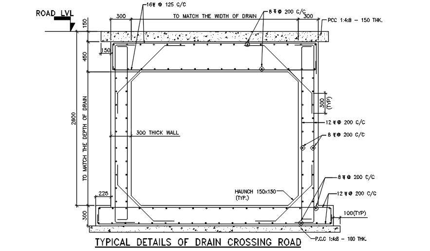
RCC Drain Box Section CAD Drawing DWG File RCC box drain under fluctuating depth of a road embankment CAD drawing which consist 100mm PCC size 300 mm bottom slab size and 300 mm wall thick size with all reinforcement detail. Precast RCC Drains We are one of the topmost manufacturers and supplier of a wide range of Precast RCC. Typical reconstruction of slab drain 600 mt.
Intercepting drains pipe drains in hill roads details of drains in cutting embankment typical cross sections 8. Autocad Drawing of a Toilet size 2400x1800 mm. Xall dimensions are in mm xdo not scale the drawing only written dimensions are to be followed.
Rcc foundations columns as per is code. One way slab two slab. Report any discrepancies.
DRAIN SECTION DETAILS SCALE. PROPOSED RCC Rcc Slab Fe 415 CC mix 100mm Plastering t2mm 150mm FCC 3 with 40mm. Retaining wall Design Design example-1 Design a cantilever retaining wall T type to retain earth for a height of 4m.
The backfill is horizontal. Necessary precaution shall be taken while excavating the foundation near by the drain. Dimensions are not to be scaled and only written dimension are to be followed.
These drains have holes and permit the collected water to get discharges into another drainage system. Drawing labels details and other text information extracted from the CAD file. 1 typical cross section 2 alignment and l - section 3 schedule.
Tertiary Drain totalling 0106km within Barguna Pourashava area under Barguna district. The engineer approval of the shop drawing must be obtained prior to commencement of work. The proposed subproject includes Construction Improvement of 7 Nos.
Sketch the drawings and detail as per the requirements. M-15 025 205 sand pcc. Plan with design of area with structural and sectional.
WIDE 28 136 50 31 50 3314 5455 40 27 50 ROAD. This structure has been designed for the following nominal loads. I Sub Drawn By Executive Engineer R NH.
Raisen mp project. Steel Plat With RCC Wall Section CAD Drawing DWG File - Cadbull. Drawing showing drainage these arrangements.
RCC Standard Drawings Drainage Author. To know prices and more details call us at. The scale is 38 inches is equal to one foot.
Unit weight of wall 23 knm3 cement concrete block unit weight of rcc 25 knm3. 36 50 15 8530 In PROPOSED WIDE 50 ROAD 21 50 50 40 130ö COMPOUND WALL 18M HIGH DRAIN 100 50 28 WITH STEEL GRATING RCC SLAB CULVERT ROAD SIDE DRAIN 114-9 14 50 41 NATURAL DRAIN NATURAL DRAIN CH. Now let us examine the cross-section for the column.
Moreton Bay Regional Council Created Date. Secondary Drains totalling 3736 km 2 Nos. Storm water drain s-02 zeroing-in on critical infrastructure gap of industrial areamandideep dist.
3 having charactertic compressive. 6 - Typical Cross section at Viaduct Portion Full Height Intersection with Kalyani Expressway Ch. The notes in this drawing shall be read in conjunction with all relevant drawing pertaining to the bridge.
Unless otherwise specified all dimensions in millimeter mm and all levels are in meter m. Span plan 110 025 240 sand pcc. Xuse concrete mix 1.
Depth is 6 inches and for the second step the depth is 6 inches. RCC Retaining Wall PCC Wall Lined Drain Approach Slab should be provided where Cross Road exists BC DBM Granular Base Granular Sub Base for Drainage Separation layers Figure. Client-typical section of rcc.
The cross section of the column will show the dimension of the column which is equal to 25 feet and the other column is 3 feet. Diploma holders in Civil Engineering will be required to supervise RCC Construction and fabrication. The density of soil is 18kNm3.
RCC DESIGN AND DRAWINGS L T P 5 - 2 RATIONALE This subject is an applied engineering subject. Brick wall beam designed for torsional bending moment section showing type bars simplified rules for curtailment of bar section through. 8x6 has got WC Basin and Shower Area.
91-9999012399 or email us at. RCC Wall Section AutoCAD Drawing Free DWG File -.

Typical Structure Detail Of Drain Floor Layout Duplex Design How To Plan

Pin On Construction Cad
Typical Drain Channel R C C Detail Autocad Dwg Plan N Design
Rcc Drain Box Section Cad Drawing Dwg File Cadbull

Typical Sump Pit Reinforcement And Structure Detail Autocad Dwg Plan N Design

Pdf Typical Section Of Storm Water Drain Rakibul Haque Academia Edu

Rcc Drainage Tank Free Download Dwg File Cadbull
Building Guidelines Drawings Section F Plumbing Sanitation Water Supply And Gas Installations
0 comments
Post a Comment